Microwave and Antenna
Experimenting and Learning
Feel free to contact me if you don't understand anything
This project is maintained by HishamElreedy
اللهم لا علم لنا الأ ما علمتنا به انك انت علام الغيوب
Microwave Introduction

Microwave signals wavelength are in centimeters not micrometers like its name

Transmission Lines
Transmission Line theory
characteristic_impedance describes the relation between electric field and magnetic field components of the propagating
wave. we have already known from previous courses of electromagnetic fields that when a wave goes from medium of
characteristic_impedance=\(\eta_o\) to another medium of characteristic_impedance=\(\eta_{load}\)
,part of the wave is reflected and part of it is transmitted and the amount power reflected and transmitted is determined by
the relation written below.
where, \({P_{reflected} \over P_{total}}= {{\eta_o - \eta_{load}} \over {\eta_o + \eta_{load}}}\)
and, \({P_{transmitted} \over P_{total}}= {{2\eta_{load}} \over {\eta_o + \eta_{load}}}\) and,
\(P_{total}=P_{reflected}+P_{transmitted}\)
so to deal with a transmission line we have to consider the same case
because we are now dealing with transmission line theory as propagation time of the wave is very close to the periodic
time of the propagating wave. where in circuit theory the propagation time of the wave is very very small than the periodic
time of the propagating wave. like in figure below, where \(\lambda\) is the wavelength of the signal,
\(\lambda={\lambda{\sqrt{\epsilon_r \mu_r}}\over{c}}\), \(c\) is the speed of light = \(3*10^8\)
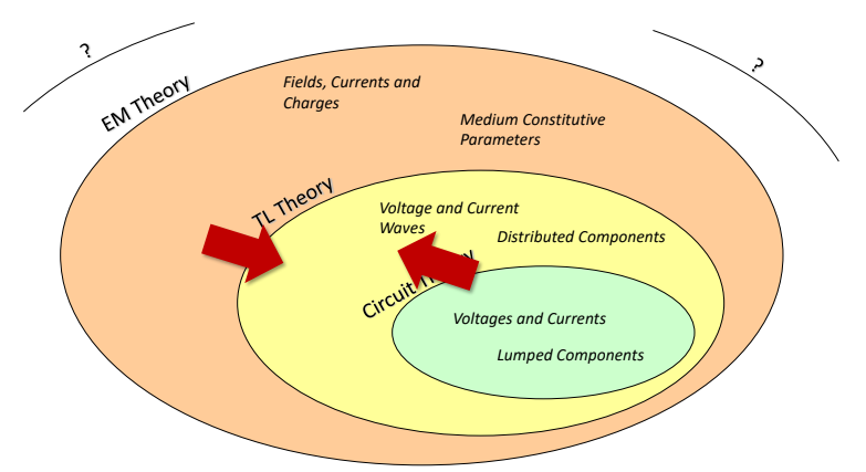
In transmission line theory, we are now taking dimensions of circuit in our consideration for calculation , where we didn't do that when we were studying electric circuits theory, that consideration made the beginning of starting courses in microwaves engineering because now we are taking space in our consideration not time only like in communication and electic circuit courses and that is the key difference why we were studying electromagnetic fields because electromagnetic theory can literally describe anything in electric engineering field but we divided This theory into a domains of validity like electric circuit & transmission line theory as show in image below like in electric circuit theory you didn't care about dimensions of inductor, resistor,..etc you were caring about its value only but in this course you will take both dimensions and value in your consideration but we will assume that time is constant at \(t_o\) while we are doing our analytical calculations
Characteristic_Impedance
when we say that medium has a characteristic_impedance this means that the medium is supporting power transfer
between electric and Magnetic Fields.
which can resemble our understanding of voltage and current waves
the ratio is large this means that I am sending using large voltage signal and small current signal
if it is small this means that I am sending using large current signal and small voltage signal. but not necessarily
that it means power loss but it means only power flow.
Transmission Line Technology
- Cable Transmission Lines
- Printed Transmission Lines
- Power Lines
- waveguides, optical fibers and other structures


Matching Networks
Old Concept of Matching
The main principle of matching network we have already passed through it while studying thevenin when you were trying where we proved that to find maximum power transfer we found that load impedance must be equal to conjugate of source impedance

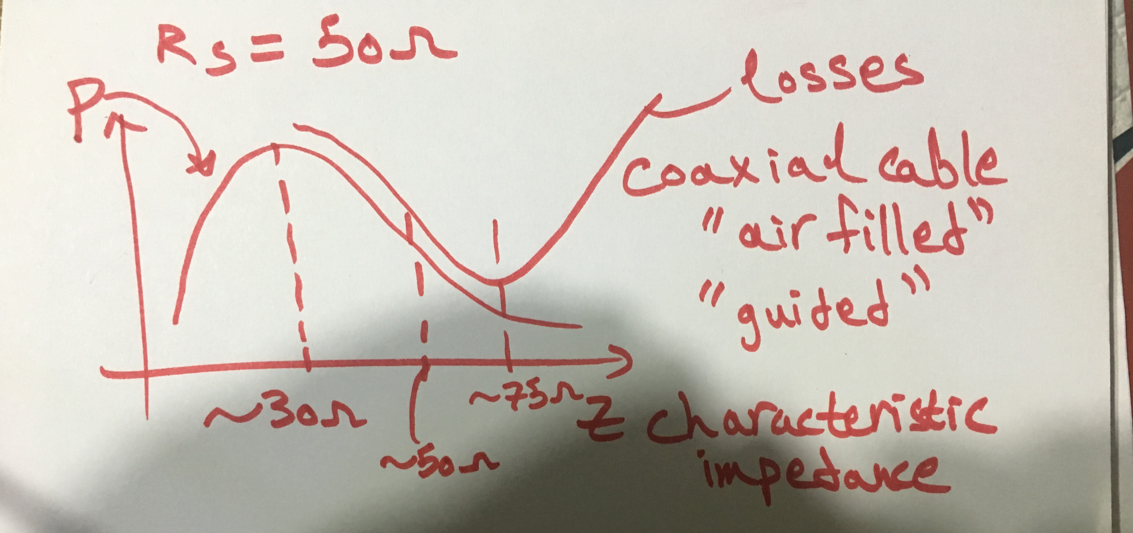
Why choosing source impedance =50ohms?
what limits power on wave guide is it will melt which we call it breakdown, we found that max power is at impedance of 30 ohms and min losses at 75 ohms in case we are using a coaxial cable air-filled so we take geometric mean of both quantities which equals 50ohms which is a standard that we usually use in antennas, filters,....and all microwave devices
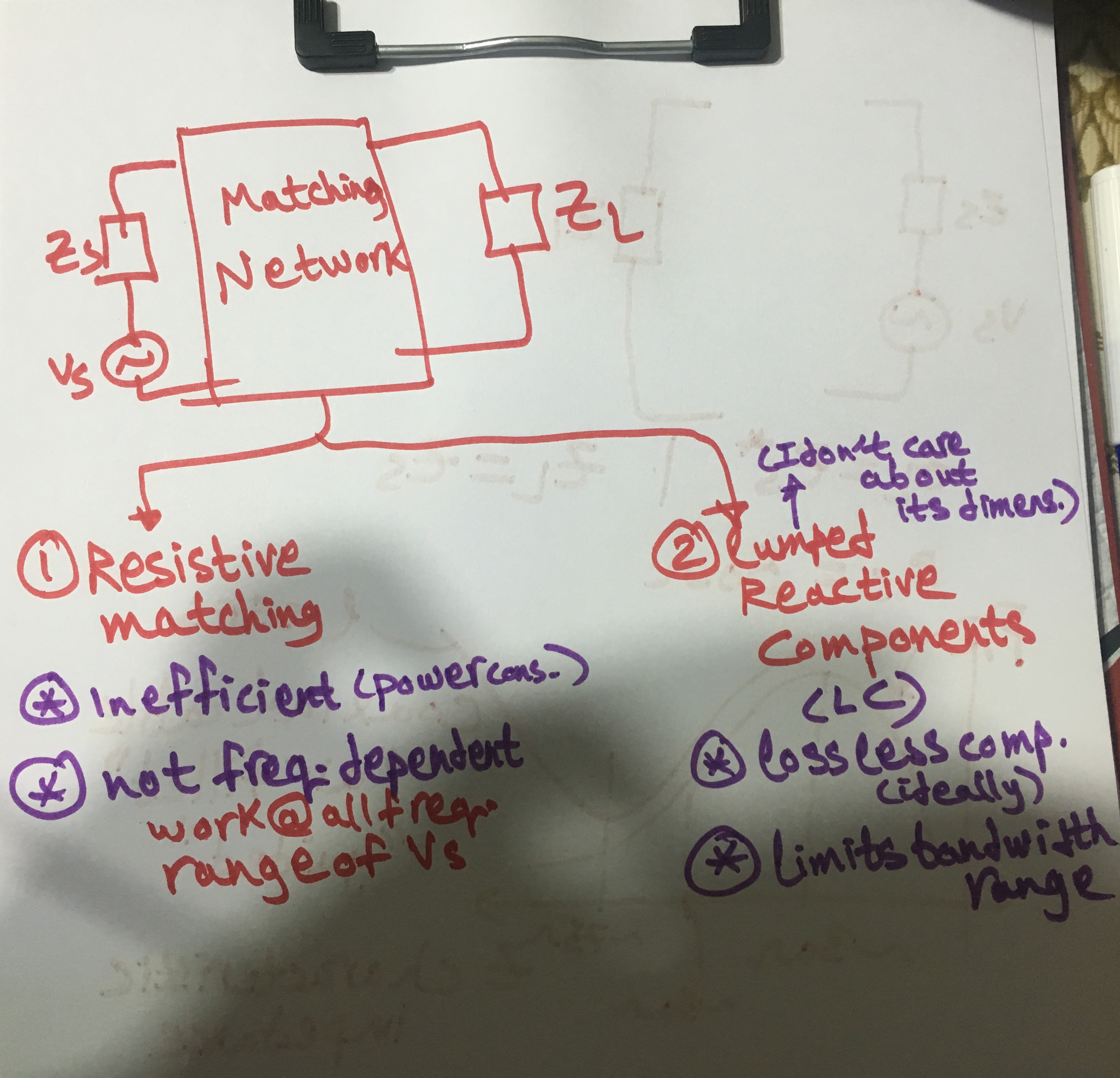
Matching using Lumped Components for a resistive load
we are trying to find matching network using lumped elements elements so we found that we have two options whether to use resistive matching where its pros that we are not limiting bandwidth range of the source but its cons that it will consume much power we are not using it as it doesn't go to the load while if we use LC-Components we will be limited by a certain bandwidth range but ideally we won't lose much power, what we mean by lumped components is it has fixed dimensions that we cannot control.
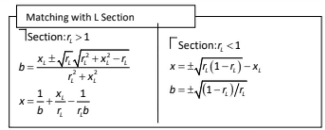
After solving equations in order to find value for values of matching network component parameters in case you are using resistive network it will be equal to geometric mean of load resistance and source resistance but in case we are using LC-components then we will have two cases when load resistance is larger than source resistance and when it is smaller like in image below where \(r_L ={ R_{load} \over R_{source} }\). where solving equation is done by getting \(Z_{in}\) equation and equating it with \(R_S\) so we will have two equations, one for real and one for imag. and solving them to find L,C values also there is another method for matching which is using transformer but it works only for a resistive load also it has effect of producing inductance from transformer coil

Matching using Lumped Components for a complex load
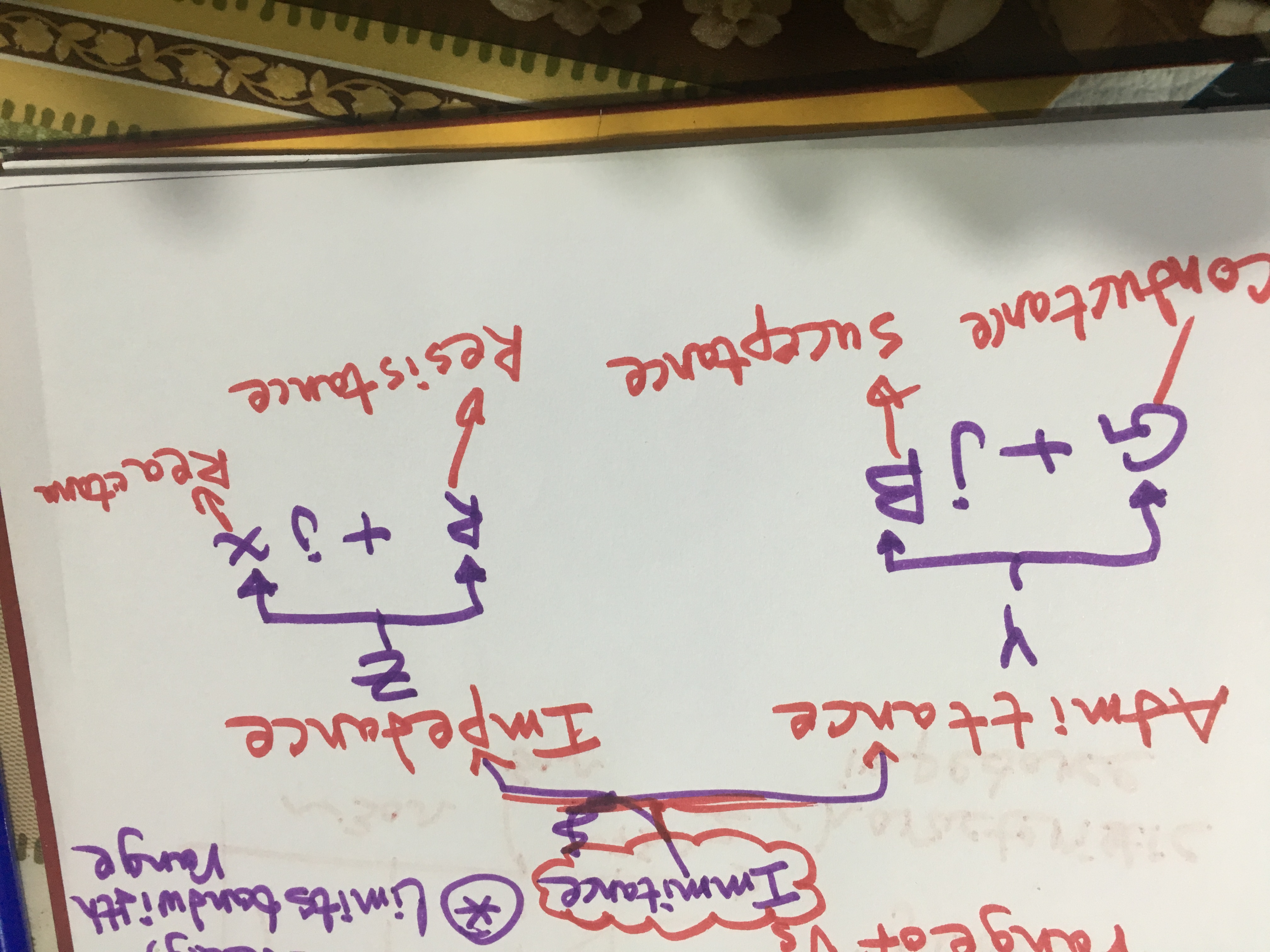
Immitance
positive reactance ====> inductive
negative reactance ====> Capacitive
positive susceptance ====> inductive
negative susceptance ====> Capacitive
Bandwidth
In communication systems when we are sending data we need to modulate the carrier signal with the message so when we are sending the transmitted signal we don't have only the carrier signal tone we have a certain bandwidth that was defined by the message when it was modulated at the carrier tone so when we design matching we need not to consider only the carrier tone but we need also to consider message bandwidth, bandwidth is defined in system requirements like 90% at center freq. Bw=1.1*f1-0.9f1=0.2*f1
